FNQ-RC "SQ5FNQ ROTOR CONTROLLER"
The description of the rotor.
Everybody complains about the accuracy and fast synchronization loss of the rotor built by CONRAD Company. The cause of this is that the rotor uses synchronic engines and, without any control, assumes that both rotate at the same pace. Unfortunately, since an antenna of defined inertia is usually installed on the rotor, its engine accelerates more slowly, which causes start and stop times to desynchronize the controller and the rotor. To solve this problem, the rotation decoder should be installed on the rotor.
Below you can see a few schemas and technical pictures.
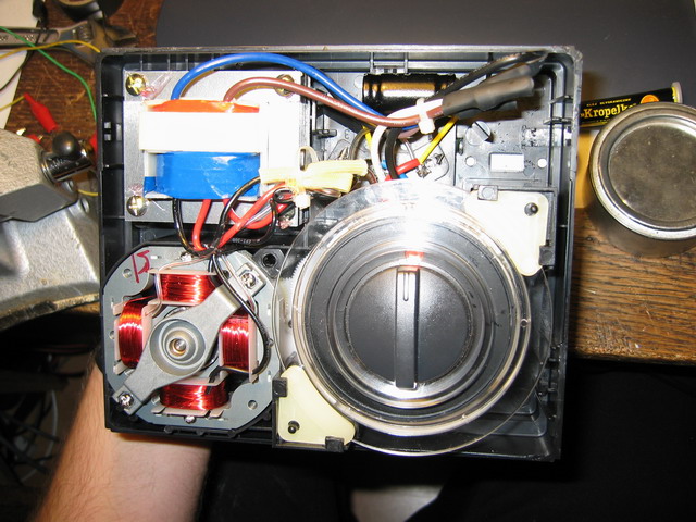
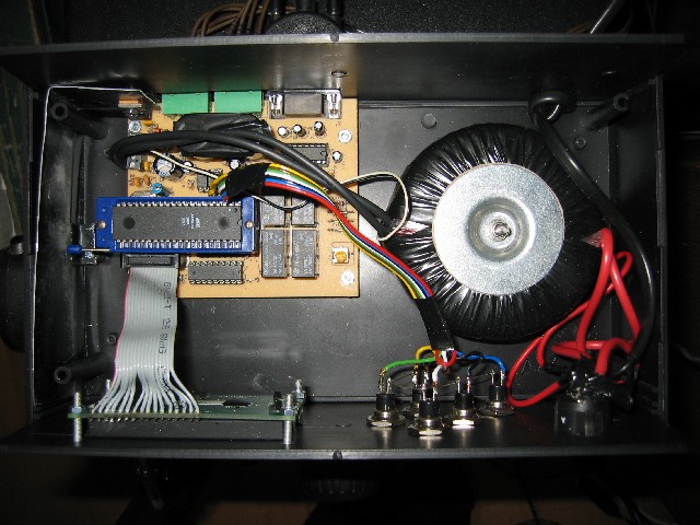
Original rotor controller.
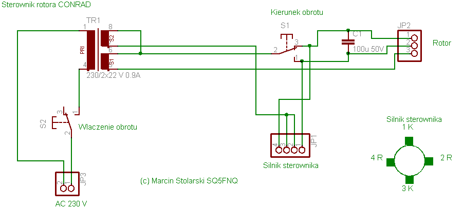
Original rotor controller schema.
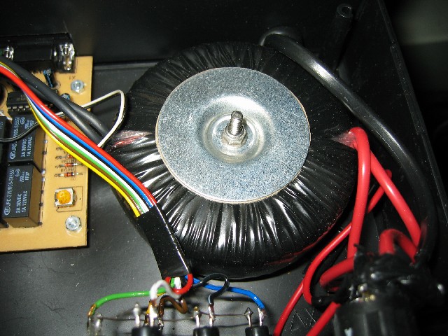
I’m not sure about the connections in the transformer, because on the output there are only 3 electrical cables and the coils can be connected in series, but this is of no importance.
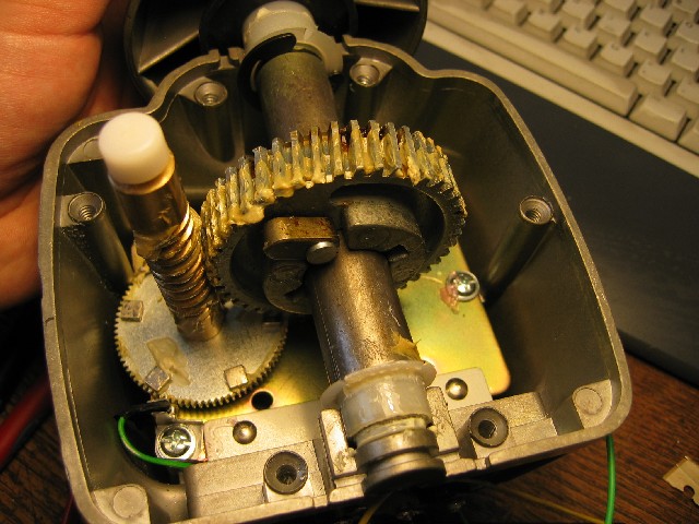
Functioning of the original rotor controller.
When we turn the controller’s knob, both switches cause the rotation of the engines in the rotor and in the controller. When the board (under the knob) reaches the knob’s position, both switches cut off the power from the engines and the engines stop.
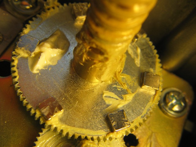
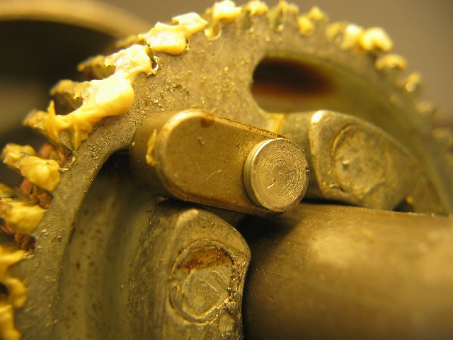
Decoder of the rotations of the rotor.
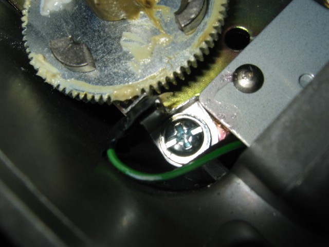
I have tried various methods of decoding the rotations of the rotor, and in my opinion, the best way is to stick (using the magnetic field) six magnets to the rack with the helix. The magnets must be stick alternately (NSNSNS; every second magnet is upside down; I have used neodymium magnets 5x5x2 mm and round ones 10x5 mm). Next on the rack’s surface we put the contactron (the smaller the better). The alternate placing of the magnets’ poles will cause the contactron to connect the electrodes near the magnets and disconnect them between the magnets. Controller counts the changes between 0 and 1 (and the other way round), which gives 12 impulses per one rotation of the rack, and 504 impulses per one full rotation of the rotor. This way we get the accuracy better than 1 degree. The controlling itself takes place with the accuracy of one degree including the inertia of the rotor.

***
The movie shows how it looks in motion.
While mounting the contactron, its glass cover must be protected (it’s easy to break it). Very important is the position in which you mount the contactron. You must mount it parallel to the area of rotating magnets (where there is the biggest variation of magnetic field).
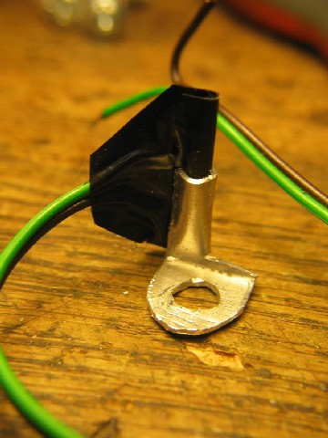
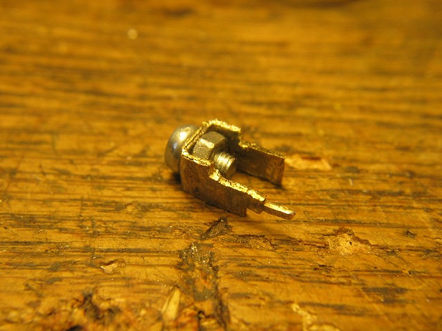
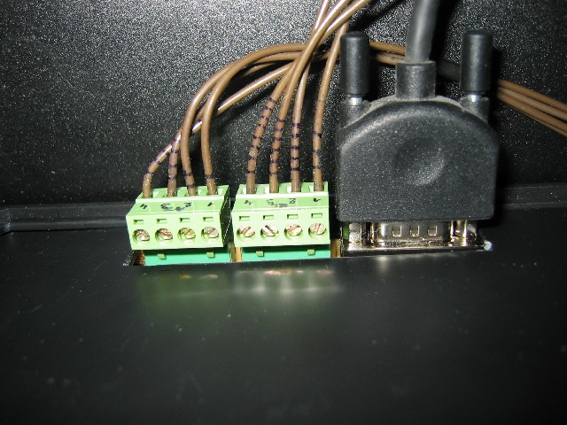
The contactron must be connected between connectors 3 and 4 of the rotor. Connector 4 can be obtained from the old controller or built like on the picture below.
The rotor can’t cross the azimuth 0 because it has a mechanical blockade. It is not good for satellite tracking because when a satellite crosses azimuth 0, the rotor must rotate the antennas by 360 degrees and it lasts about 70 seconds. It is possible to remove it but then the rotor can break down the antenna cables. If somebody has an idea how to change this blockade for rotating the rotor by about 450 degrees, send me an e-mail. For now I have added a software solution. When you send to the controller a command to set the position to AZ=390 and EL=10, the controller switches to the REVERSE MODE and rotates the antennas system to the position AZR=AZ-180=190 and ELR=180-EL=170. For this operation, the rotor needs less then 45 seconds. The next software solution is a blocker detector. For example if the rotor rotates to the left and the blockade stops the rotation, the controller will detect it as synchronization error and correct the position value to 0. On the right side it will set the value of 360. For elevation the value will be either 0 or 180.
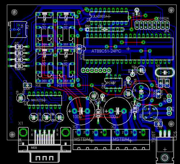
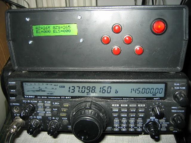
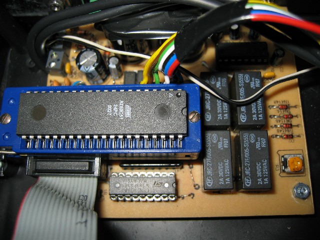
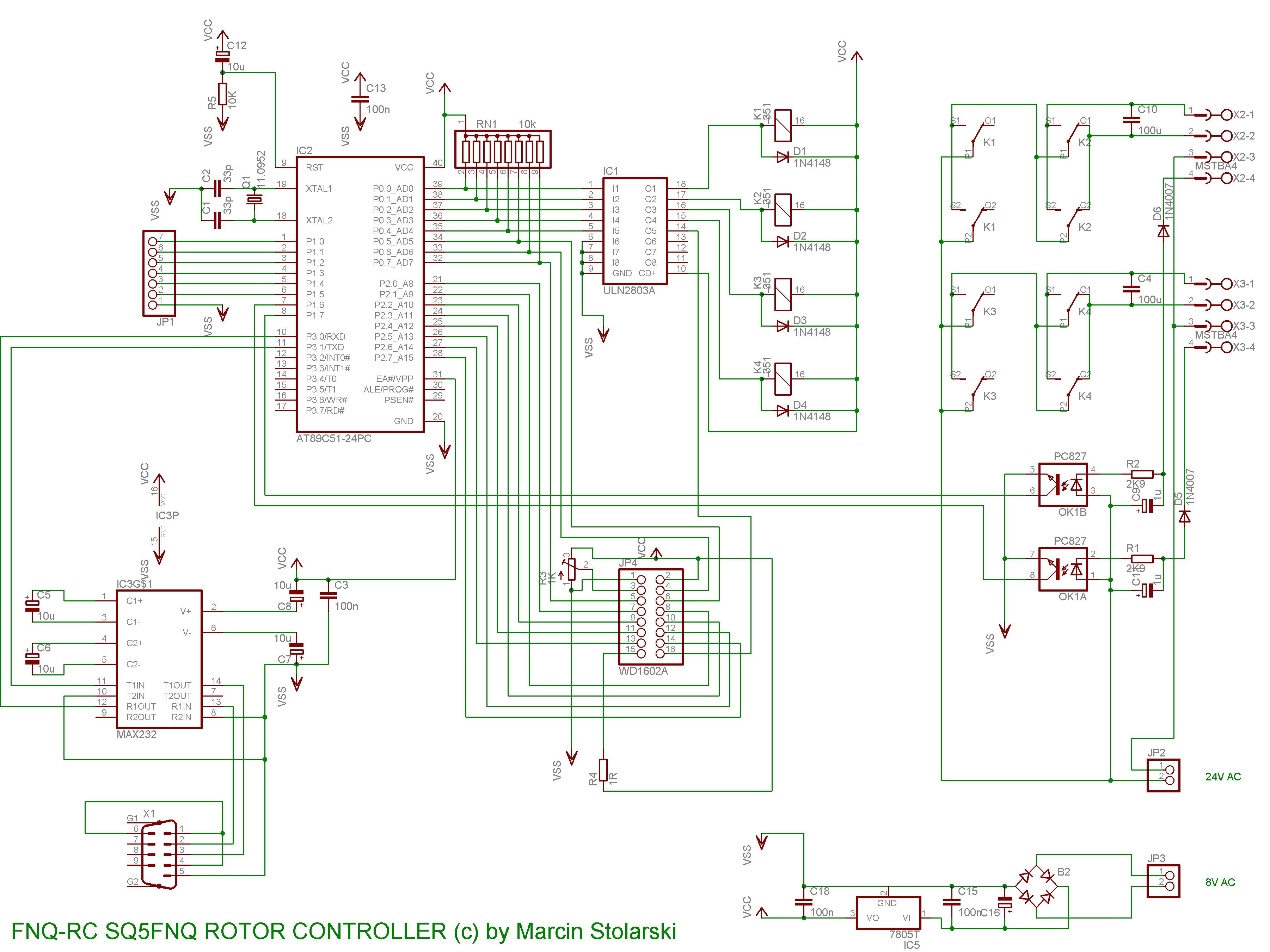
Electronic controller.
Since no one volunteered to build an electronic controller, I began to do it myself J. I used the AT89C51 microcontroller. The controller has two isolated electrical circuits (for controlling the power of the rotor and for the logical electronics of the controller). For isolating this circuit I used relays and transoptors (optical isolators).
The controller has buttons for rotating the antennas manually (LEFT, RIGHT, UP, DOWN). The additional button is for entering the MENU, where you can park antennas system, set on/off backlight, set on/off RS232 communication and restart the controller. Unfortunately the controller doesn’t have an EEPROM so all settings will be lost if you cut the power off. If you lose synchronization (switch off the controller when the antennas system is not at the position (0, 0) ) you need to park the rotor before you use it again. On the LCD screen you can see the position of the antennas system (AZ, EL), the programmed position by the RS232 port (AZS, ELS), the direction of rotating system (L, R, U, D) and information about the REVERSE MODE (R). For computer control you need to use the YAESU GE-232A protocol. It is probably the most popular protocol in the world. This protocol is present in such applications as the Orbitron or the WXtoImg. The controller receives commands “Maaa” and “Waaa eee”. You can use the controller for rotating azimuth only with one rotor or azimuth and elevation using two rotors. For communication, the controller uses 9600bps RS232 baud rate.
For powering, the controller needs two isolated AC electrical sources (22V 2A and 8V 0.5A). In prototype I have used 80VA 24V 3A transformer. I have added an 8V coil. It is important that the added coil is isolated from the 24V coil. You need it for electrical separation of logical modules inside the controller.
For connecting the controller with the rotor I have used two cables with 4 wires (in particular I have used four 60 meters cables with 2 wires named PKL, which is a cable for military telephones, but I used it because I have it J). For connecting the controller to the computer I have used RS232 NULL MODEM cable.
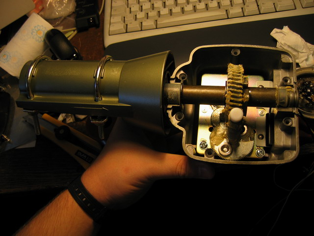
Rotor mechanism.
For satellite tracking you need the rotor for azimuth and elevation rotating. Commercial satellite rotors are very expensive and cost about 1000 USD (3500 PLN). I have built low cost rotor (lower than 300 USD (1000 PLN)). I have used two CONRAD company rotors (2x 50 USD), added two ball-bearings (2x 20USD) and a few aluminum pipes (diameter 35mm). The cost of building the controller is about 50 USD.
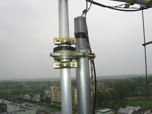
The mounting of the azimuth rotor is typical, with additional ball-bearings for strengthening the construction.
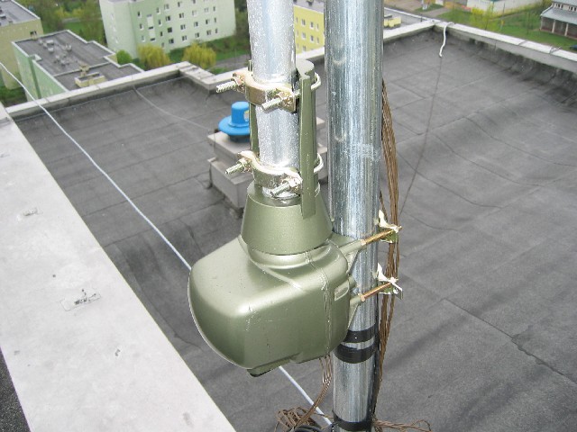
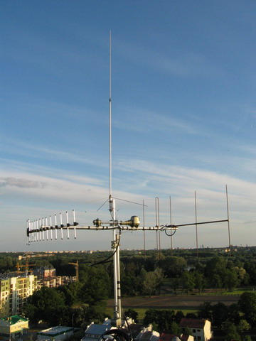
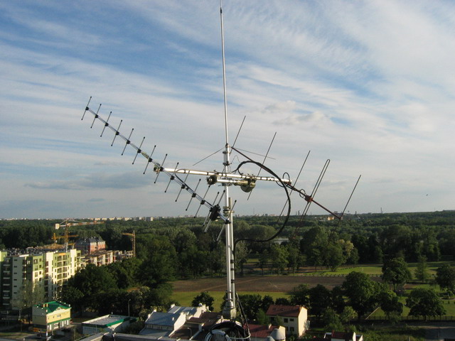
I have mounted the elevation rotor like on the picture below. I suggest using good cross mounting connection between pipes. I have added stabilization for antenna cables using the PKL cable. For connecting the antennas to the radio I have used the H1000 cable but this cable is not designed for bending. In this configuration the rotor can rotate by 180 degrees. The mast is used as a mechanical blocker. Additionally, the GP antenna can be installed on the mast. In my installation I have used GP 2x7/8 at 145MHz, 5 elements YAGI at 145 MHz and 15 elements YAGI at 435 MHz. In the future I’m going to add the 2.4 GHz antenna. For connecting the system with my home I have used the H155 (HF, GP), H1000 (YAGI), PKL (rotor) and RG6U (2.4 GHz down converter) cables.

Power budget of antennas system:
· 145MHz = 6.2dBi
o 60m H1000 = -2.9dB
o 5 elements YAGI = 9.1dBi
· 435MHz = 9.7dBi
o 60m H1000 = -5.1dB
o 15 elements YAGI = 14.8dBi
I use this construction to connect with radio amateur satellites. I can receive telemetry from cubesats. I can work in 9600bps G3RUH mode etc.
Conclusions:
How my construction works, you can see on the movie.
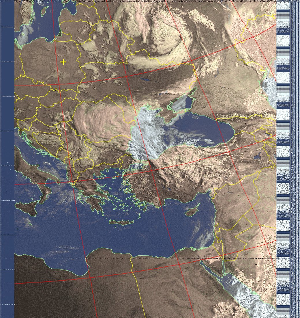
Finally you can see the photo from NOAA 15 satellite. To receive this picture I have used my rotor, Yaesu FT-847 transceiver (using short FM modulation) and WXtoImg application.
NOTICES:
If somebody would like to build this rotor system, send me an e-mail. As an answer I will send you the password for materials (PCB, schema, firmware etc.). My salary will consist in the photo of your system and comments to this project which I add to my gallery J.
Gallery:
Here you can view the photos of the devices build by other people.
Regards...
Marcin
SQ5FNQ
Status:
Prototype testing.